TEM Setup for Analysis
Before you start an experiment, it is important that the TEM is well aligned. The emitter, condenser and optic axis adjustments typical for your TEM type should be performed. This will help maximize image brightness and minimize lens aberrations.
-
Insert your sample into the column (if possible, first plasma clean the sample).
-
Find the region of interest you want to investigate.

-
Align the TEM; critical for energy-filtered TEM (EFTEM).
-
Set TEM to eucentric focus value and bring the sample to the eucentric height.
-
Check the condenser alignment.
-
Align the optic axis (use HT-centering if available; alternatively rotation center or coma-free centering can be used).
-
Clear the beam path to the filter (retract unused detectors and raise viewing screen).
-
-
From the user interface on your TEM, enter the Gatan imaging filter (GIF) or EFTEM lens series (if available) for your TEM.
Note: The GIF or EFTEM lens series serves two critical functions.-
Stabilizes the position of the projector crossover so the EELS spectrum will stay in focus at the slit for all TEM magnifications.
-
It lowers the apparent magnification of the TEM to compensate for the increased magnification of the GIF to allow a larger field of view as well as easier control of the TEM stage and adjustments.
-
-

Select Unfiltered.
Prepare the GIF for imaging.
Note: It is often useful to locate the GIF field to view relative to the screen center. Identify a prominent feature in the sample on the GIF camera, then lower the viewing screen. Make a note of the position of the feature relative to the screen center.-
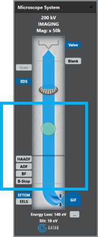
From the Microscope System palette in the DigitalMicrograph® 3 software.
-
Select the EFTEM control button to place the GIF in image mode.
-
Right-click on the EFTEM control button to select Unfiltered from the Regime dropdown list.
-
-
Double click on the GIF camera icon within the Microscope System palette to start the camera view or select View from the Camera palette in the Techniques Manager.

Select View.
-
You should now have an image of the specimen on the view screen. If no image appears.
-
Ensure the screen is lifted and no other detectors are in the beam path.
-
With the screen down, check that the central area of the screen is illuminated.
-
-
-
-
Preview filtered image.
-
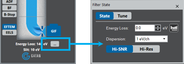
Choose Zero-Loss regime from the dropdown list or simply check the Insert Slit box.

Choose Zero-Loss regime.

Or check the Insert Slit box.

-
If necessary, run the Center ZLP command to center zero-loss peak within the slit.
-
-
Take a thickness (\(t/\lambda\)) map.

- Under EFTEM technique, choose the \(t/\lambda\) button.
- If the buttons are not visible, make sure SingleMap mode is selected in the EFTEM pallet.
- As a default, choose Auto checkboxes for the Exposure and CCD binning settings.
- Choose OK to acquire the map.
 Evaluate the local thickness (in mfp) of the sample from the thickness map and compare to the typical required values above.
- Under EFTEM technique, choose the \(t/\lambda\) button.